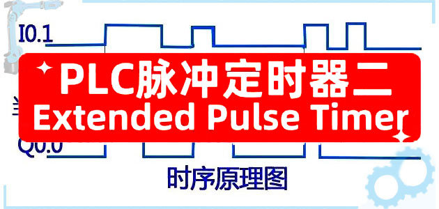
Five commonly used PLC timers-Extended Pulse Timer (2)
post time:2024-04-10 16:52:29 author:Free Little Bird clicks:1342 【 Size:big middle small 】
Timers are commonly used instructions in PLC programming, but sometimes we often confuse their functions, resulting in subsequent program debugging or maintenance work. A friend once lost production because he didn't figure out this timer, so he was embarrassed in front of customer leaders and colleagues. In order to avoid friends repeating the same mistakes, the next 5 articles will sort out the functions and uses of these 5 commonly used PLC timers.
This article will talk about the Extended Pulse Timer.
1. Overall working principle
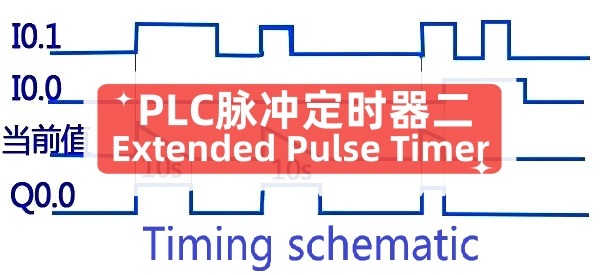
When the signal at the input end is 1, the output is 1, the output time length is the set time, and the output is stopped when the set time reaches 0. Even if the input signal changes from 1 to 0 within the set time, the output continues to output the signal 1, the time length is the set time, and the output stops when the set time reaches 0.
Compared with the Pulse Timer function mentioned in the previous article, it will be clearer: the basic condition for the pulse timer to have a signal output is that there is an energy current signal at the input end, and when the input signal is disconnected, the output is also disconnected.
2. What it looks like in the ladder diagram of PLC programming.
PLC Extended PulseTimer PLC
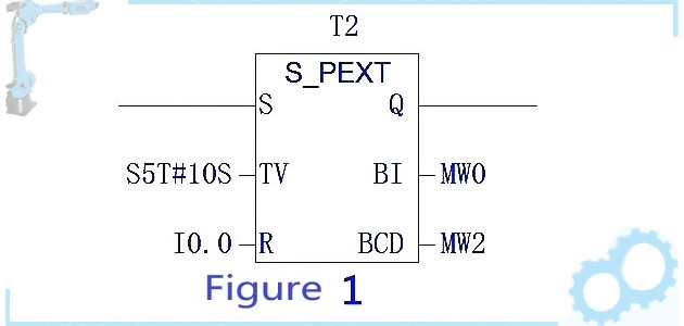
In the above figure, the S end is the signal input terminal; The TV side is the preset value input side, which is the timing time you want to set, and IOS is set here; The R end is the reset end; Bl and BCD are output to display the current time value, the display value type is different, Bl is a hexadecimal format without a time reference, and BCD is S5T# format.
3. Programming examples and timing diagram explanations
PLC programming example application
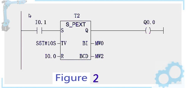
In the above figure, 10.1 is the start button, the control signal is interrupted, when pressed, the IOS timing starts as shown in Figure 3 below, and there is a signal output (QO.O gets the signal), the IOS timing ends, stop the output, if you release the button within the set IOS time, continue to output until the set IOS time reaches 0, stop the output when the current time is 0, QO.O has no signal as shown in Figure 4 below. When the 10.1 reset button (when pressed, the timer output is 0, the signal output stops) is shown in Figure 5 below.
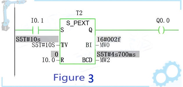
Green indicates the PLC energy flow opening state
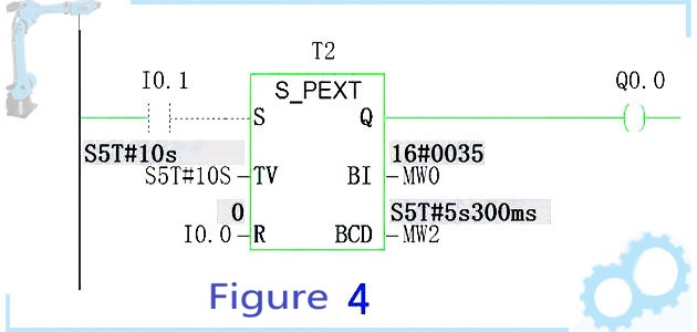
The timer continues even if the input is disconnected
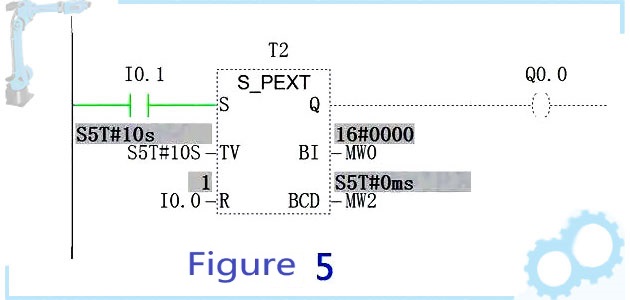
When the reset button is pressed, the current value is set to 0 and the input is stopped
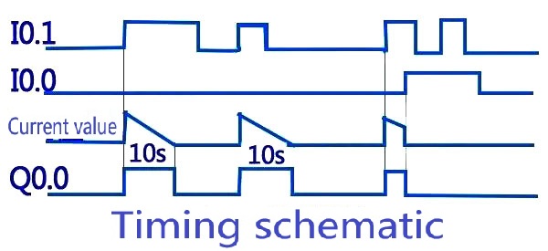
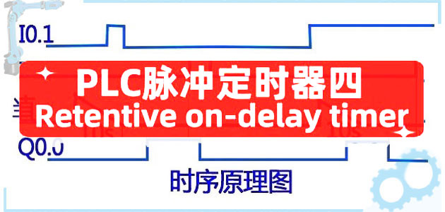
The corresponding timing diagram on the PLC
The above is the timing schematic diagram of their counterparts. In order to help friends deepen their impression, here I leave you two small questions to think about: When the timer is halfway through, release the start button iO.1, does the timer stop output? When the start button is released and the timer is halfway through (5s), when the start button is pressed again, does the timer start from the beginning (IOS) or from the middle (5s)?
If you want to learn systematically, please pay attention to private chat with me! Thank you!

 X
X
Guess you like

Application and development of PLC technology in smart home
 2488
2488 What is PLC and how does it work? -Understanding PLC
2712 How does the PLCjudge the fault through the fault indicator of the CPU?
2321 What is the meaning of the CPU mode selector switch in PLC?
2047 Five commonly used PLC timers to comb out the Off-Delay Timer (5)
2075 Retentive on-delay timer of five commonly used PLC timers (4)
1626 
At the critical moment, he walked away again

Application and development of PLC technology in smart home

(2)2-Xiao Zhang accepted a bribe - twists and turns and lessons

The role of relays in new energy vehicles: a comparison with traditional fuel vehicles
Bearings play an important role in improving the power of new energy vehicles
Gear reducer analysis introduction
New energy vehicle planetary reducer: the advantages are highlighted, leading the future transmission technology
New energy vehicle reducer

Planetary gears for new energy vehicles: a key technology to improve power transmission efficiency

(2) 1 - Xiao Zhang was blocked

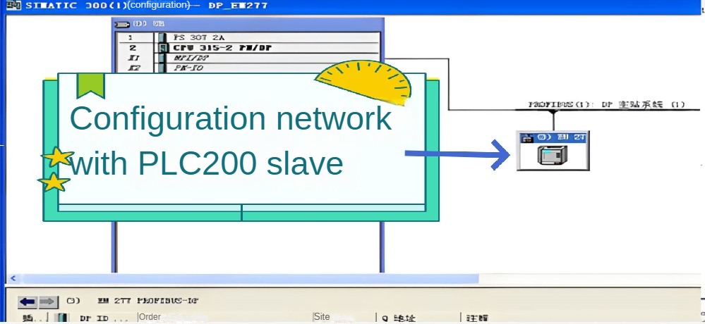
How does the PLC-200 series communicate with the PLC-300 series CPU?
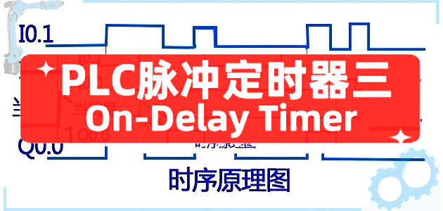
Five commonly used PLC timers on-delay timer (3)
New energy vehicle reducer
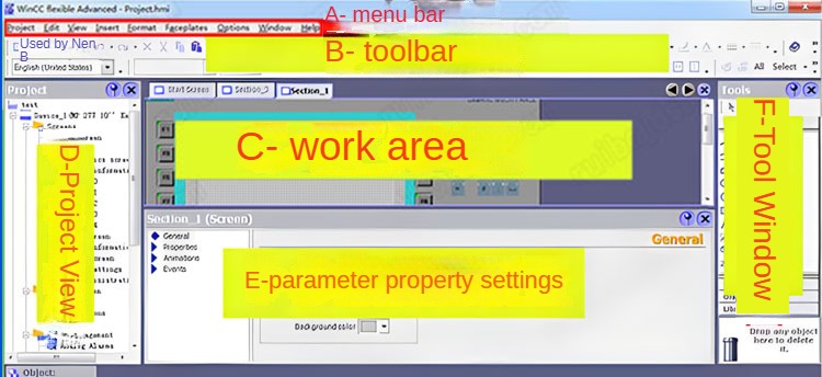
How to edit the touch screen interface corresponding to PLC?
Five commonly used PLC timers-Extended Pulse Timer (2)
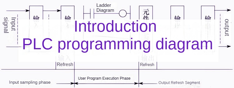
PLC programming introductory illustration
Retentive on-delay timer of five commonly used PLC timers (4)
What is the data structure in PLC programming?

New energy vehicle planetary reducer: the advantages are highlighted, leading the future transmission technology
(2)2-Xiao Zhang accepted a bribe - twists and turns and lessons
What is PLC and how does it work? -Understanding PLC
Application and development of PLC technology in smart home
Planetary gears for new energy vehicles: a key technology to improve power transmission efficiency
Gear reducer analysis introduction
How does the PLCjudge the fault through the fault indicator of the CPU?
New energy vehicle planetary reducer: the advantages are highlighted, leading the future transmission technology
Five commonly used PLC timers to comb out the Off-Delay Timer (5)
What is the meaning of the CPU mode selector switch in PLC?
New energy vehicle reducer
The role of relays in new energy vehicles: a comparison with traditional fuel vehicles